An electromagnetic flow meter gives reliable liquid-flow data only when the fluid, pipe geometry, installation and signal conditions match the instrument specification. By the end, you will be able to check conductivity, size the meter, compare alternative technologies, prevent common installation errors and interpret the accuracy claim before you buy.
Key takeaways
- Confirm the liquid’s conductivity before selecting an electromagnetic flow meter.
- Match bore size and flow range to your actual operating conditions.
- Keep the pipe full and provide straight, disturbance-free installation.
- Compare accuracy at your normal flow rate, not only the headline figure.
How an electromagnetic flow meter measures liquid flow—and when it cannot
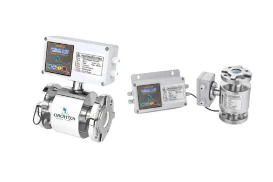
An electromagnetic flow meter calculates volumetric flow from the voltage produced when a conductive liquid moves through a magnetic field. This is Faraday’s law: electrodes detect the induced voltage, which rises with liquid velocity; the transmitter combines that signal with the pipe’s measured area to calculate flow.
With no rotor, turbine or impeller, the meter adds little obstruction to a full-bore pipe.
The liquid must exceed the instrument’s minimum conductivity specification. A 5 µS/cm minimum is common in some industrial designs, but it is not universal; check the selected meter’s datasheet and test a representative liquid sample at its operating temperature before purchase.
| Liquid condition | What happens | Decision |
|---|---|---|
| Conductive water or wastewater above the specified threshold | Stable electrode signal | Suitable, if the pipe remains full |
| Deionized or highly purified water | Conductivity can fall below the threshold | Verify the exact specification before selection |
| Hydrocarbons, oils and many solvents | Insufficient conductivity for electrode measurement | Use another meter technology |
| Conductive slurry | Measurement is possible, but coating and abrasion can affect electrodes and liner | Confirm materials and maintenance needs |
Above the conductivity limit, density and viscosity have little effect on the reading. Entrained air, coated electrodes and poor liquid contact still create noise or bias, so prevent air admission and avoid locations where bubbles separate from the liquid.
Specify the bore, flow range and wetted materials before choosing a meter
Choose the meter bore from operating data, not simply the pipe diameter. Oversizing lowers liquid velocity and places normal flow near the converter’s lower range, where a fixed accuracy component becomes more significant.
Provide these values before requesting a quotation:
- Minimum flow, normal flow, maximum flow and any planned future flow
- Target velocity range, including the lowest velocity that must remain measurable
- Operating pressure, design pressure and pressure or vacuum transients
- Minimum, normal and maximum liquid temperature
- Liner material and electrode material, matched to the liquid’s chemistry
- Flange standard, such as ASME B16.5 Class 150 or EN 1092-1 PN16
| Specification detail | What to provide | Why it determines the meter |
|---|---|---|
| Pipe diameter and bore | Nominal size, inside diameter and wall lining | Confirms the measuring tube fits without creating an unsuitable velocity |
| Flow range | Minimum, normal, maximum and future flow | Prevents routine operation at the bottom or top of the calibrated range |
| Velocity range | Required low and high liquid velocity | Exposes an oversized bore before purchase |
| Pressure and temperature | Operating and design limits | Sets the body, liner, gasket and flange ratings |
| Wetted materials | Liner and electrode chemistry | Prevents swelling, corrosion, coating or signal loss |
| Flange standard | ASME, EN or another named standard, plus rating | Ensures the meter matches the existing pipework |
Check chemical compatibility at the actual concentration and temperature, not against water alone. Confirm the selected liner and electrode pair with the manufacturer’s compatibility chart; an acceptable body rating cannot rescue an incompatible wetted material.
Install the meter so the pipe stays full and the signal stays clean
A meter installed at a high point, downstream of a free discharge, or in a partially filled gravity line can read falsely low or fluctuate. Install it in a consistently full pipe, not where entrained air separates from the liquid. If the line cannot stay full, use a meter designed for partially filled conduits.
Leave the specified straight run around the meter. Pumps, partially closed valves, tees, reducers, elbows and expansions disturb the velocity profile; follow the manufacturer’s distance for the exact upstream arrangement instead of assuming magnetic meters need no straight run.
Grounding is part of the measurement circuit, not just a safety measure. Bond the meter, adjacent pipe sections and the liquid reference to the same potential. Lined or plastic pipe, insulating gaskets and cathodic-protection systems often require grounding rings, reference electrodes or a dedicated grounding arrangement.
Incorrect bonding allows electrical noise, drifting output and zero offset.
Check the installation before commissioning:
- Set the electrode orientation approximately horizontal. This keeps air from collecting across the electrodes and prevents suspended solids from settling directly on the lower electrode.
- Bond grounding rings on both sides where the pipe is nonconductive or lined; confirm continuity across insulating gaskets.
- Prevent air admission at pump suction points and high spots. Air bubbles interrupt electrode contact and destabilise the signal.
- Check for electrode coating when the liquid contains solids or deposits.
- Verify that changing conductivity matches the meter’s operating limits, then enable empty-pipe detection so a drained tube cannot appear to measure flow.
Read the accuracy specification at your actual operating flow
At 100 m³/h, a meter rated ±0.5% of reading allows an error of ±0.5 m³/h. A ±0.5% percentage of full scale claim on a 1,000 m³/h meter allows ±5 m³/h at the same flow. Near minimum flow, that difference can overwhelm the measurement.
Confirm what the percentage uses: the live reading, calibrated span, or full-scale output. Also check whether the stated figure combines repeatability, zero error, and transmitter performance. The lower range limit marks where the manufacturer stops guaranteeing that accuracy; operation below it is not made reliable by a favourable headline percentage.
Oversizing creates this problem. Select the bore using minimum, normal, maximum, and future flow, then check velocity at each point instead of matching the nominal pipe diameter alone. A large tube can place everyday flow near the bottom of the usable range.
For billing, regulatory reporting, or custody transfer, put these acceptance details in writing:
- The required uncertainty at each operating flow, not only one accuracy percentage.
- Calibration points spanning minimum, normal, and maximum flow.
- Calibration method and traceability to a named national or international standard.
- Whether testing covers the complete meter assembly, including the transmitter, or only one component.
- Installation conditions, including a full measuring tube and specified grounding.
Repeatability shows whether readings agree with one another; it does not prove accuracy. Zero error shifts the result even when repeatability is excellent. Test the installed meter under representative conditions before relying on its output for invoices.
Choose between electromagnetic, insertion, ultrasonic and mechanical meters
A full-bore electromagnetic meter fits a conductive liquid in a full, accessible pipe where low pressure loss and bidirectional flow matter. Choose an insertion electromagnetic meter for large pipes or retrofit work when shutting down and cutting the line is difficult; verify its insertion depth and velocity profile.
A clamp-on ultrasonic meter avoids pipe penetration and suits temporary surveys, but bubbles, poor coupling and uncertain wall thickness can reduce stability. A mechanical meter suits clean liquid and modest budgets, but moving parts wear, foul and add pressure loss. For remote monitoring, specify the output protocol and totalizer behavior, not only the local display.
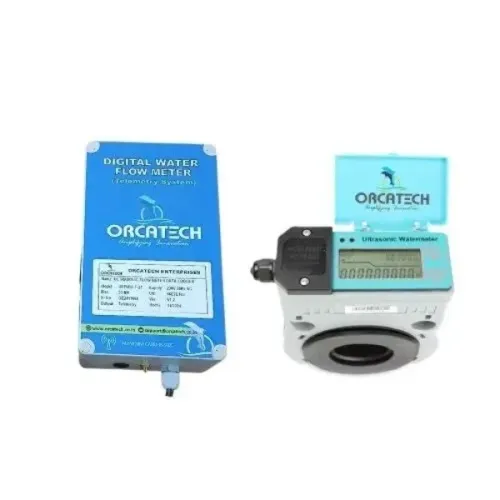
Orcatech Enterprises can help compare telemetry equipment against the site’s flow range and data-logging needs.
| Option | Best fit | Main risk or limitation |
|---|---|---|
| Full-bore electromagnetic meter | Conductive liquid, permanently full pipe, accurate continuous measurement | Electrode coating, grounding faults or an empty pipe can corrupt readings |
| Insertion electromagnetic meter | Large-diameter or retrofit lines where shutdown is difficult | Installation profile and local turbulence affect accuracy |
| Clamp-on ultrasonic meter | No-cut installation, temporary checks or difficult access | Coupling, bubbles and pipe data affect the signal |
| Mechanical meter | Clean liquid with simple local indication | Wear, blockage and pressure loss |
- Accuracy as percent of reading or full scale, required uncertainty, calibration traceability and calibration points at minimum, normal and maximum flow.
- Complete-assembly acceptance testing, including installation conditions, full-pipe status, reverse-flow indication, pulse scaling, totalizer logic and remote-monitoring data.
- Materials, pressure and temperature limits, straight-run requirements, outputs, alarm behavior and the procedure for handling a failed test.
Frequently asked questions
When can an electromagnetic flow meter not measure liquid flow?
It cannot measure non-conductive liquids, and it gives unreliable results when the pipe is not full or the electrodes lose proper contact with the liquid.
What should you specify before choosing an electromagnetic flow meter?
Specify the nominal bore, minimum and maximum flow, operating temperature and pressure, liquid conductivity, and wetted materials.
How should you install an electromagnetic flow meter?
Install it where the pipe remains full, follow the manufacturer’s straight-run requirements, ground the meter correctly, and keep it away from pumps, valves and electrical interference.
How should you compare flow-meter accuracy?
Check the accuracy specification at your normal operating flow, minimum flow and maximum flow, including zero stability and repeatability.
When is another flow-meter type a better choice?
Choose insertion, ultrasonic or mechanical meters when the liquid is non-conductive, the pipe cannot remain full, installation access is limited, or the application requires a different measurement method.