A pressure reading from a subsurface sensor is not automatically the regional groundwater-table elevation. You will be able to identify what a piezometer is measuring, convert pressure into hydraulic head, choose the right instrument, and judge whether a reported water-level change is real.
Key takeaways
- A piezometer measures pressure at its intake depth, not automatically the regional water table.
- Convert pressure to hydraulic head using sensor elevation and water density.
- Use short screened intervals and seals to avoid connecting separate aquifers.
- Check barometric pressure, sensor drift, and nearby measurements before accepting a change.
What a Piezometer Measures at a Specific Depth
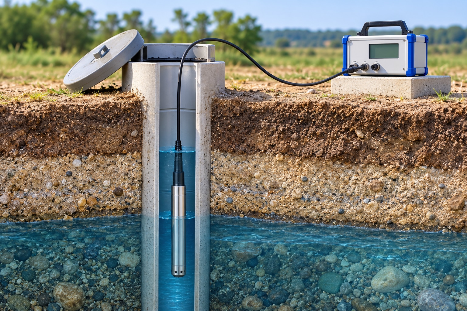
A piezometer reports pressure at its intake depth, not automatically the elevation of the regional water table. Its screened or porous interval selects the hydraulic zone being measured; a long screen can average pressure across several metres, while a poor seal can connect aquifers with different pressures.
| Term | What it means | What the measurement tells you |
|---|---|---|
| Pore-water pressure | Pressure carried by water in soil or rock voids at the intake point | Stress conditions at that depth; it is not a surface elevation |
| Hydraulic head | Elevation head plus pressure head: h = z + u/(ρg) | The energy level used to compare groundwater flow between points |
| Groundwater elevation | The elevation of a water table or potentiometric surface above a stated datum | The water level’s height, not its depth below ground |
| Water-table depth | Vertical distance from a chosen ground or reference point down to the unconfined water table | How far below that reference the water table lies |
| Piezometer reading | The instrument’s pressure, or pressure converted to head, at its intake | Conditions in the isolated screened zone |
A monitoring well commonly has a larger open or screened interval and is used to observe a water level; a piezometer targets a defined depth. A standpipe piezometer shows pressure through a water column, while vibrating-wire and pneumatic piezometers sense pressure electronically or through gas.
A pressure-transducer logger records pressure over time, but it becomes a water-level record only after you apply sensor elevation, datum, atmospheric pressure where required, and fluid density.
How Pressure Becomes Water Level or Hydraulic Head
A piezometer converts pressure into a useful water-level elevation by dividing measured pressure by the fluid’s unit weight and adding the pressure point’s elevation. The pressure-to-head relationship is pressure head = pressure ÷ (water density × local gravity); hydraulic head = sensor elevation + pressure head.
Use the same vertical datum for the sensor elevation and the resulting head. In a confined aquifer, that result is the potentiometric level, not necessarily the water-table elevation.
Near ordinary field temperatures, 1 m of water head is approximately 9.81 kPa, 1 kPa is approximately 0.102 m, and 1 cm is approximately 98 Pa. Exact values change with water density and local gravity. Temperature affects both the sensor and fluid density, so temperature compensation does not replace site checks.
Record these with the pressure series:
- Sensor elevation, including the elevation of the intake when it differs from the sensor.
- Vertical datum, such as a site benchmark tied to a recognised elevation system.
- Water density or the calculation basis used to estimate it.
- Fluid temperature when density or sensor response changes with temperature.
- Barometric pressure for an absolute transducer. A vented transducer references atmosphere through its vent tube.
- An independent electric-tape or steel-tape reading, with its reference-point elevation and timestamp.
- Pressure units, time zone, sampling interval, and whether the recorded value is absolute or gauge pressure.
Choosing the Sensor for Aquifers and Geotechnical Sites
Choose the sensing arrangement by site depth, required response time, pressure range, and the consequences of failure. A shallow aquifer with occasional manual checks does not need the same instrument as a dam foundation requiring continuous pore-pressure data.
| Option | Best fit | Main decision |
|---|---|---|
| Standpipe piezometer | Shallow groundwater, excavations, and low-frequency surveys | Simple and durable, but readings require access and equilibration; it cannot show rapid pressure changes well |
| Vibrating-wire piezometer | Embankments, dams, foundations, and long-term geotechnical monitoring | Stable digital readings over long cable runs; specify the pressure range and temperature performance |
| Pneumatic piezometer | Embankments or contaminated sites where the sensor stays outside the water | Keeps electronics away from aggressive water; tubing length and response lag become important |
| Pressure-transducer logger | Deep boreholes and aquifers needing unattended time-series data | Records small changes automatically; choose vented or absolute measurement and provide barometric compensation for absolute data |
Use a standpipe piezometer for a shallow, accessible point when hourly or daily readings are enough. Select a vibrating-wire piezometer for dam cores, earth fills, and foundations where durability and long-term stability matter. A pneumatic piezometer suits contaminated water when replaceable tubing and an isolated sensor reduce chemical exposure.
For a deep borehole, match the transducer range to the maximum water column; excessive range sacrifices resolution. In a contaminated site, confirm wetted-material compatibility and keep the screened interval dedicated to the target zone.
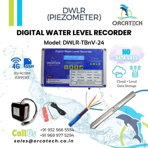
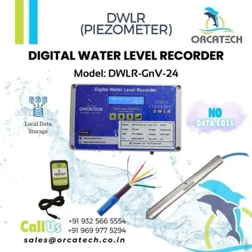
Orcatech Enterprises supplies digital water-level recording systems, but the recorder is the data layer, not the piezometer selection. For geotechnical pore pressure, check the installation and instrument specification against ISO 18674-3.
Related products
 | Digital Water Level Recorder (DWLR) ₹51330 Digital Water Level Recorder, Telemetry with Local Data Storage, Grid Operated, Cloud Application, Digital Reporting View product → |
 | Digital Water Level Recorder (DWLR) ₹62304 Digital Water Level Recorder, Telemetry with Local Data Storage, Grid Operated, Cloud Application, Digital Reporting View product → |
Installing the Intake Without Connecting Different Aquifers
Make the intake short and place it only in the stratum whose pressure you need to measure. A long screened interval averages pressure across its height, while an intake that crosses an aquitard can connect zones with different hydraulic heads.
- Drill a borehole diameter that leaves enough annular space to place the filter pack and seal continuously; an oversized, irregular annulus is difficult to fill reliably.
- Set casing through unstable formations, then position the screen or porous tip entirely within the target layer. Keep the screened interval clear of adjacent aquifers and do not bridge a confining clay or silt layer.
- Place a clean, graded sand pack around the screen. Select its grain size for the formation and screen opening so formation fines stay out without choking groundwater flow.
- Install a low-permeability bentonite seal above the sand pack, and use a bottom plug where the construction allows it. Place and hydrate bentonite as specified; gaps create a vertical leakage path.
- Fill the remaining annulus with cement-based grout above the seal. Do not grout across the intake or allow grout to enter the screen.
- Finish with a cap, lockable protective cover, and a raised or flush monument that sheds surface water. Mark the reference elevation and protect it from vehicles, runoff, and later disturbance.
A clogged porous tip, screen, or sand pack slows equilibration and hides real pressure changes. A poorly filtered intake admits fines, causing fouling and unstable readings. In low-permeability ground, wait for formation recovery before treating the first reading as representative.
Checking Whether a Recorded Water-Level Change Is Real
Treat a small change as unconfirmed until an independent measurement supports it. Compare the logger with an electric tape or steel tape from a documented reference point, using the same vertical datum; comparing one logger reading with the previous reading can hide drift or a changed installation elevation.
- Select a pressure range that covers the highest expected pressure without wasting resolution at normal conditions. Sensor resolution is the displayed increment, not measurement accuracy; calibration uncertainty, hysteresis, drift, temperature, and datum errors can exceed that increment.
- For vented versus absolute pressure, inspect the measurement method. A vented transducer references atmospheric pressure through a vent tube; protect the tube from water, blockage, kinks, and condensation. An absolute transducer uses a sealed vacuum, so pair its record with a barometric-pressure logger and apply the correction.
- Apply temperature compensation, then check the result against tape readings because both the sensor and water density change with temperature.
- Allow the intake and surrounding formation to equilibrate after installation or purging. A reading taken too soon can represent disturbed water, not formation pressure.
- Inspect the intake for sediment, biofilm, mineral scale, and chemical fouling; clean or replace it under the installation procedure rather than interpreting a sluggish response as stable groundwater.
- Secure the logger, strain-relieve the cable, record cable length and sensor elevation, and prevent cable movement from pulling the sensor or changing its depth. Recheck zero, clock time, datum, and sensor elevation after servicing.
Frequently asked questions
What does a piezometer measure at a specific depth?
It measures hydraulic pressure at its screened or porous intake interval. A long screen can average pressure across several metres, while a poor seal can mix readings from different aquifers.
How does piezometer pressure become water level or hydraulic head?
Convert pressure to water-column height, then reference that height to the sensor elevation. The result is hydraulic head, which allows readings from different elevations to be compared.
How do you install a piezometer without connecting different aquifers?
Place the intake in the target hydraulic zone, use a short screened interval, and seal the annulus with suitable grout or bentonite above and below the intake.
How can you check whether a recorded water-level change is real?
Check barometric pressure, sensor drift, battery and data gaps, then compare the result with manual measurements and nearby wells before treating the change as groundwater movement.
Related product
 | Digital Water Level Recorder (DWLR) ₹83544 Digital Water Level Recorder, Telemetry with Local Data Storage, Battery Operated, Cloud Application, Digital Reporting View product → |